|
Reception of ON0TVO on
10 GHz
 |
| By the calculations we know that we
could expect about -77,2 dbm on the entry of the antenna, so I
wondered in how far the theoretical calculations would correspond to the
practical measured signals.
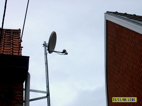
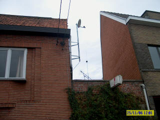
My antenna is a 40 cm dish at about 7m
height AGL and looking in the length direction of my street shoring my
neighbors houses. At 500m I look between the roofs of some houses
further on in the street.
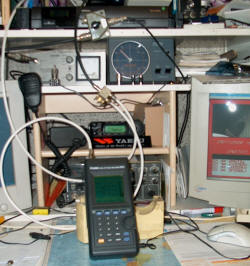
The shack is just beneath the antenna
so that I have only 10m of coax between the LNB and the sat tuner. |
 |
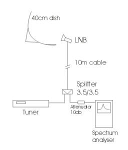 |
Setup:
On the left you can see the schematic
setup op the reception.
The antenna is a 40 cm dish with a
modified Sat-TV LNB
To bring the signal down on 1.180 GHz I
use Belden cable H125 having 23db attenuation pet 100m on 1.2 GHz. So
the attenuation of the cable and the connectors until the splitter is
+/- 3 db
The splitter is a 2x 3.5db one.
In the path to the spectrum analyzer
there is a 10 db attenuator and counting an other 0.5db for the
connectors between the spec.anal and the splitter. So from the
entry of the splitter, (the point normally connected to the sat tuner) I
count an attenuation of 14 db. |
|
|
|
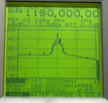
On the left one can see that the signal. The
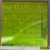
strength is fluctuating between -12dBm and -16dBm. On the right you can see in
the upper level the signal level 1dBm (taken in account here the 14 dB
attenuation) in the middle you can see the noise flour of -24dBm and the third
value is difference. So we have a nice 25dB over the noice flour what result in
an B5++ image.
Calculating back, assuming 0dBm on the splitter we have
on the exit of the LNB 3dBm.
A MF gain of the LNB of 50 dB and an antenna gain of 30
db gives us -77 dBm signal in the air.
So the
calculated signal of -77.2 dBm seems to be correct what we messure.
